Blog
5-Axis Machining for Complex Parts: Fewer Setups, Better Accuracy
Angled holes, curved transitions, faces in five directions: how 5-axis CNC machining cuts setups, holds features to one datum, and when 3-axis is enough.
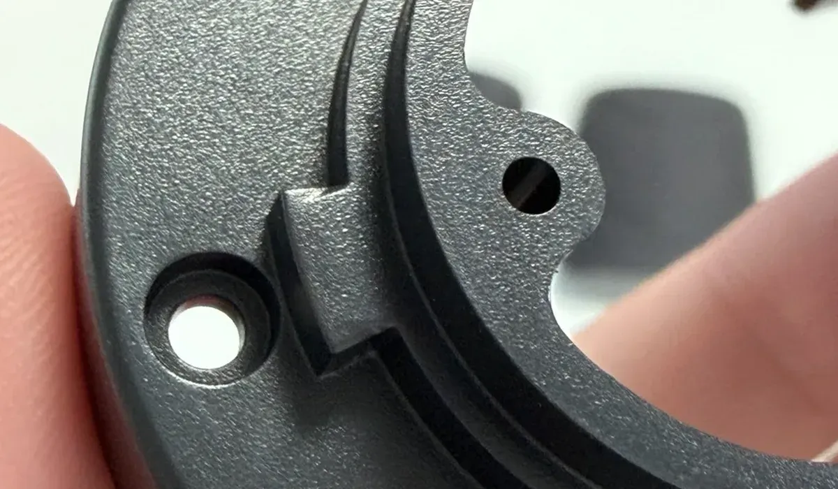
Some parts sit neatly on a milling table and can be finished from one or two sides. Others have angled holes, curved transitions, deep pockets, and important faces pointing in several directions. An upright, a complex housing, or a bracket that wraps around neighboring components can spend as much time being repositioned as it spends being cut.
That is the problem 5-axis CNC machining is meant to solve. Used on the right part, it reduces setups, keeps related features aligned to the same datums, and makes shapes practical that would be slow or awkward on a 3-axis machine. Used on the wrong part, it adds cost without adding value. The useful question is not whether 5-axis sounds advanced. It is whether the geometry of your part benefits from it.
What 5-Axis Actually Means
A conventional 3-axis mill moves the tool in three straight directions: left to right, front to back, and up and down. A 5-axis machine adds two rotational movements. Either the table, the spindle head, or both can tilt and rotate, changing the angle between the cutter and the part.
In plain terms, the tool can approach the workpiece from many more angles during one setup. An angled port does not always require a special fixture, and a face on the side of a housing can be machined without unclamping the part and starting again.
Five-axis machining does not remove the need for good workholding, tool selection, or programming. What changes is how much of the part can be completed before those decisions have to be reset.
Why One Setup Matters
Every time a part is removed and fixtured again, its position has to be established again. A skilled machinist can do that accurately, but each new setup introduces another opportunity for a small offset. Those offsets matter when features on different faces must line up with each other.
Keeping the part in one setup protects the relationship between features. A bore on one face, an angled hole on another, and a locating surface underneath can all be machined from the same datum structure. That consistency is valuable on components where several interfaces meet: uprights, gearbox or pump housings, sensor mounts, and brackets that locate more than one assembly.
Less handling also means fewer fixture changes and repeated measurements, which helps keep small batches moving.
Our standard machining tolerance is ±0.1 mm, with ±0.01 mm achievable where a feature calls for it. Our milling envelope is up to 700×450×300 mm. The point of 5-axis machining is not to tighten every number on a drawing. It is to hold the important relationships between features while the part is still located in a known position.
Part Types That Benefit Most
The strongest candidates usually share one trait: important geometry does not live on parallel faces.
Uprights and housings with angled features are a natural fit. Ports, pockets, and mounting faces may point in different directions, and their relative positions affect the assembly. Machining them in one setup helps those relationships stay consistent.
Complex brackets also benefit when they turn corners, carry bosses on several planes, or need lightening pockets that follow a load path rather than a simple rectangular outline. A bracket can look small and still be a poor candidate for repeated manual repositioning.
Parts with faces on several planes — enclosures with side ports, manifolds with angled entries, and mounts that combine a flat base with inclined features — often need fewer compromises on a 5-axis machine. The cutter can meet each face at a sensible angle instead of forcing one setup to serve every direction.
When 5-Axis Is Overkill
Honest advice matters here. A flat plate with drilled holes, a simple block with pockets from one side, or a straightforward bracket with two perpendicular faces is usually faster and cheaper on a 3-axis machine. Programming and proving out a 5-axis job for that geometry buys very little.
The same applies when only one minor feature is angled. It may be more economical to machine the bulk of the part on 3-axis equipment and handle the angled hole or face in a planned second operation. The right process depends on how many features benefit, how they relate to each other, and how many parts are needed.
Designing With 5-Axis in Mind
Five-axis access is wide, but it is not unlimited. A cutter is a physical tool with a diameter, a holder, and a limited reach. Deep narrow pockets, sharp internal corners, and features hidden behind other geometry can still be difficult or impossible to machine as drawn.
Give the tool a path in. Where function allows, use internal radii that a real cutter can produce, avoid unnecessary depth in narrow pockets, and think about how a tool approaches an angled hole without striking the surrounding part. If a feature sits inside a cavity, ask whether there is a clear line of access from any direction.
It also helps to identify the functional datums early. Which face locates the part in the assembly? Which bores or holes control alignment? If those relationships are clear on the drawing, the setup can be planned around them. Call out ±0.01 mm only where fit, motion, or alignment requires it; leave non-critical features at the standard tolerance so machining and inspection time goes where it counts.
Finally, send the 3D model with the drawing. Complex geometry is easier to assess from the model, while the drawing carries the tolerances, threads, and finish requirements. Together they let the shop check access, estimate setups, and raise manufacturability questions before metal is cut.
If your part has angled features, several working faces, or interfaces that must stay aligned, send it for a manufacturability check and quote. You can start with our 5-axis machining services or compare the wider options on our CNC machining page. We reply within 8 hours, and quotes are usually back within 24 hours.